I’m confused with the schematics for this project.
The 10k LED resistor is not connected to anything nor is 4.7k resistor. I’m assuming that the 2 red wires in the top right should be moved 1 column to the left to connect to these resistors. At the moment they are not connected to anything.
A circuit diagram would be helpful here, not only to debug Fritzing errors but to help us newbies see how a circuit translates into real life.
A description of what actually goes on would be invaluable. Even If I get the project working I will still have no idea what the Trigger, Discharge, Threshold etc do.
Thanks,
Andrew
Hi Andrew,
Thank you for bringing that up. That is definitely something that I’ve tried to improve over the years and I agree that those schematics are hard to follow, but that was one of my first projects that I’ve ever shared online back in 2013.
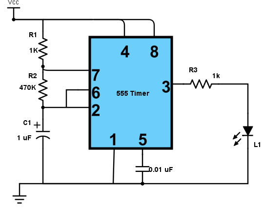
In the oscilloscope project, I use a 555 timer flasher circuit. Here’s a similar circuit diagram that will also work:

The circuit diagram above was taken from this Unit of the Electronics for Beginners course: https://rntlab.com/flashing-an-led-with-the-555-timer
I hope this helps and please let me know if the Electronics for Beginners Unit helps.
Thanks,
Rui
Thanks Rui,
This is the first project I’ve attempted since I joined. I’ve had a look at the Beginners Unit and realise I should have started there for the basics.
Sorry to have bothered you.
Thanks again,
Andrew