I am using ESP32 and i need to switch on power to numerous sensors that use about 100 mA. The digital pins do not have enough amperage and thus i want a small switch triggered by a pin out high to allow power in directly from the 3.3 v power supply and another to let vin to a power booster to power a 12v sensor. It was suggested to split the power supply to three or so pins to split the load, but i have no more spare pins. I have tried the SIP-1A03 (PAN CHANG) relay which in theory is perfect, but sometimes it does not let go, the power stays on and drains the batteries ( I am trying ways to make it reliable with no success). There are many AC relays for home automation but these are an over kill, too big and consume too much power for a simple 100 mA application. I heard that transistors can be used, i have S8050 but could not get it to work. Are there any tutorial on how to make a low power relay for a 3.3v trigger. I did see the robotdyn thyristor for AC on ebay and flip flop switch on ebay that might work, but i want to learn how can i build it myself for direct implementation on a PCB board.
Hi
try
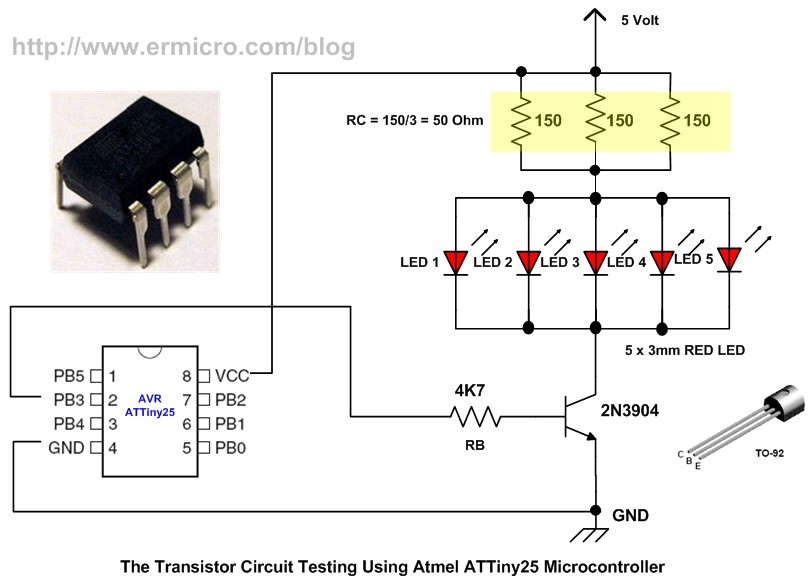
http://www.ermicro.com/blog/?p=423
TIP120 Transistor
5mA from pin to produce 5A 1000 hfe
use PWM up to 8A
2N3904 Transistor
max current 200mA
output Voltage 40V
rs-online.com/designspark/basics-of-2n3904
https://www.youtube.com/watch?v=A9zeEuDNzvA
Logic Level Converter 3,3v to 5v and 5v back to 3.3v
Relays
- https://www.youtube.com/watch?v=nMgvKgqA0JI
- banggood.com/BESTEP-1-Channel-3_3V-Low-Level-Trigger-Relay-Module-Optocoupler-Isolation-Terminal-For-Arduino-p-1355736.html?rmmds=search&cur_warehouse=CN
- banggood.com/DC12V-ESP8266-Four-Channel-Wifi-Relay-IOT-Smart-Home-Phone-APP-Remote-Control-Switch-p-1317255.html?rmmds=search&cur_warehouse=CN
Thank you very much. I have ordered a 2N3904 and I am doing the calculations to be ready. Please check my logic an calculations below to check if I understood. I am using the calculations outlined in http://www.ermicro.com/blog/?p=423 .
I have a 3.3v pin out form a IO from my ESP32 to supply to the base, I will be needing to supply 50 mA to a group of sensors. According to the data sheet for the 2N3904 https://www.sparkfun.com/datasheets/Components/2N3904.pdf the hfe for 50 mA is 60.
IB = IC / hFE = 0.05 / 60 = 0.00083 A or 0.83 mA
RB = (VPORT – VBE) / IB
RB =(3.3v – 0.7v)/ 0.00083 = 3132 ohms
So all I need is to apply a 3.1K ohm resistor to bring the down the voltage to about 0.7v to the base and limit the amps to about 0.83 mA.
I interpret from the diagram that the transistor is a switch that connects the load to ground. So all of my sensors will have power in them, but the current will not flow because ground is not connected?
However can I put the load on the other side of the transistor so the transistor will switch the power going onto the sensors. Some of my sensors are in moist soil and thus I feel nervous of supplying them with constant power and only switching off and on the connection to ground.
I often take off and put on sensors. The calculations assume all my sensors pull 50 mA, what will happen if I disconnect some sensors and they only pull 25 mA or I add on a few extra sensors and they draw 75 mA, will the switch still work? Can I just build the transistor for a 100 mA draw (780 ohm RB) and it will be OK if I only put on enough sensors to draw 25 mA?
Hi
Yes 3.1K ohm resistor
use 1% tolerance 0.4w
All the grounds ie transistor(containing its 12v supply) and esp32 must be connected together
https://roboindia.com/tutorials/switching-transistor-nodemcu/
http://www.ermicro.com/blog/wp-content/uploads/2009/11/trsw18.jpg
transistor as switch
use esp32 instead of Arduino
https://www.youtube.com/watch?v=WRm2oUw4owE
https://www.youtube.com/watch?v=WxKBI96CY1Y
https://www.youtube.com/watch?v=2OzzHbbe4V8
https://www.youtube.com/watch?v=R0Uy4EL4xWs
https://learn.sparkfun.com/tutorials/transistors/applications-i-switches
http://www.zen22142.zen.co.uk/Design/bjtsw.htm
http://www.penguintutor.com/electronics/beginner1
Hope it helps
Thank you all
I have just tried the 2N7000 to switch a red led (in line with a 70 ohm resistor) using a 3.3v power source and it only worked after I had to put a 10K ohm pull down resistor on the gate. A very strange result occurred that perhaps someone can explain was that every time I touched the gate with a wire of any sort it turned on the transistor switch, this wire was not connected to a power source. I did make sure the transistor was the right way around, I found that if you switch drain with source it just powers it on permanently like reversing a diode. My only interpretation (I am a novice) was that the floating voltage in the wire was activating the transistor, but when I used a 10K resistor as a pull down all worked fine. The 2N7000 does have a min gate activation voltage of 0.8, so perhaps the floating voltage was enough to activate it???. Any one else had this occur to them or do they have an sound explanation?
I will also try the 2N3904 when it arrives in the mail, at least I have the 2N7000 working on the bread board and hopefully working will in the application after I solder it in.