The PIR 501 5v sensor will not pick up motion after uploading sketch. it is the 5v 501 sensor. the sketch loads fine but nothing else. I copied and pasted the sketch so there would not be a problem
Hi Mike,
If you want us to help you, maybe you can make a little effort to describe your problem more precisely… What project are you trying to implement? With which microcontroller? What wiring diagram did you follow? What code did you upload? If you don’t give any precise details about what you want to do and what you’ve done, I doubt we can help you efficiently.
Hi Mike.
Can you tell me what project are you trying to follow and more information regarding your setup (camera board that you’re using, etc?)
I also recommend checking with a multimeter or oscilloscope if your PIR sensor is working as expected. Measure if it is outputting a signal or 5V when motion is detected.
Regards,
Sara
Working on the esp32 course, using the wiring diagram in the course with equipment suggested in module 2 working on motion sensor with interrupts. I have 5v supplied to the esp32 board. There is not a camera on the board. I have tried 2 different pir motion sensors of the type required.
Hey Mike,
The operating voltage of your sensor is 5V by default. However, the ESP32 operates on 3.3V (even if it is supplied with 5V). You must therefore use a little trick to make your sensor work in 3.3V.
Here is an article that explains the trick to use:
Cheap Pyroelectric Infrared PIR Motion Sensor on 3.3v
I have a cheap sensor that I got in an Arduino starter kit ordered somewhere in China with which I did a test and it works very well.
Here is my own wiring:

- the red cable is connected to 3.3V pin of the ESP32,
- the black cable is connected to the GND pin of the ESP32,
- and the white cable is connected to the data read pin on the ESP32.
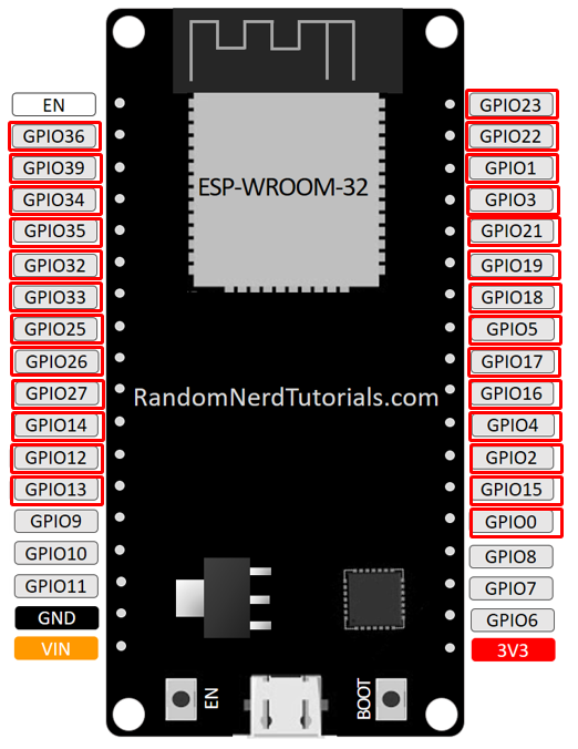
For your project, if you wish to use interrupts, you can choose any of the data read pins from those marked with a red rectangle :

I think everything should be fine with this little trick 😉
Let us know!
[EDIT] after some reading on Rui & Sara’s website
I found an article where they mention exactly what I suggested above:
Modifying Cheap PIR Motion Sensor to Work at 3.3V
So, on the face of it, we’re all good 🙂
Hi Mike.
Can you try what Stéphane suggested and see if it works?
Also, double-check with a multimeter that your PIR sensor is working properly.
Regards,
Sara
i found the 5vPIR/full size works okay on witty that doesn’t have 3v3 out.
Or, if feeding VIN.5v instead of going thru usb as pwr. on other major boards
Seems bucks down to 3v3 when motion sensed/switch closes, so can feed back as input to be sensed high
Otherwise, i use the baby PIR that seems ok 3v3 in and out
First off I want to thank you for taking the time to help me out. Second thing is I’m a dumba$$. I had the negative wire in the wrong spot on the motion sensor and on the breadboard. I contribute part of this to the meds I have been on since my surgery but not all of it. I did hook up to the 3.3 v like Stephane suggested. The only thing that is not right yet is the LED is not lighting up and that maybe the resistor I have on it. But all is good now and on the the next part of the course.
Hi Mike.
Don’t worry, we all make silly mistakes. Happens to me all the time.
What matters, is that it is working now.
But about the LED, double-check that you have the negative and positive leads of the LED on the right orientation. What resistor are you using?
Regards,
Sara
Hey Mike,
Glad to know your PIR sensor’s working now.
As far as the LED is concerned, you need to make sure that you add a series resistor with an R value that allows your LED to emit enough light. However, R depends on three factors:
- the voltage supplied by the control pin of the ESP32 (U = 3.3 V)
- the forward voltage Uf of the LED (which depends on its colour)
- the current I flowing through the LED so that it lights up without being damaged

For standard LEDs, a current of 20 mA is recommended.
I have performed forward voltage (Uf) measurements on some of my LEDs, which are quite standard:

And here’s a conversion table that should help you determine the best resistance you have at your disposal:

Here, a resistor of 100 Ω is more than enough for any LED.