I was working on the above project and when I got to the section:
After having the temperature value stored in the temperatureValue variable, you need to set the temperatureValueLabel text to the value received by the sensor.
We also change the label color accordingly to temperature reading:
- blue if the temperature is lower than 5 ºC
- green if the temperature is between 5 ºC and 25 ºC
- red if the temperature is higher than 25 ºC.
I was not able to see how the three overlapping “get global temperature” blocks were obtained sitting on top of blue blocks in the three ” if then” control blocks.
in other words where did these blue blocks whose main body is covered by the “get global temperature” came about.
there is a small section shown with the entry “< \/ ” and then 5 or 25. that last part I understand but I for the life of me I can not reproduce the blue long block, no matter what combination of actions I have tried.
may i know this is already solved or not? I it is solved please share the solution.
Hi.
I’m sorry for the delay in my response.
I’m not really sure if I understood your question.
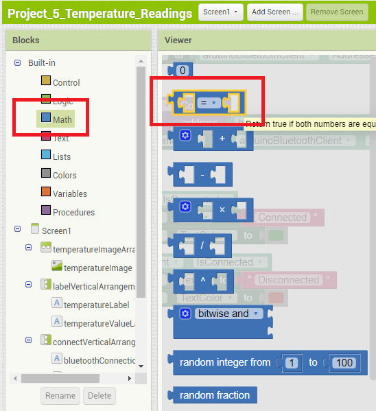
To reproduce those blue blocks, in the Blocks tab, go to Math and select the following block as shown below:

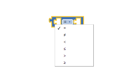
Drag that block to the blocks editor area. Then, you can choose which operation you want to do if you click the “=” sign:

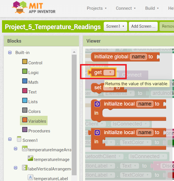
Then, in the Blocks tab, select Variables and then drag the block highlighted bellow to the blue block you’ve added previously:

Then, in that block, you just need to select the global variable that you want.
Let me know if this helps.
Regards,
Sara
Thank you Sara,
I was able to complete this assignment with your help. It was really simple but nevertheless this project with these three if then blocks should have been elucidated so that novices in this app, do not get frustrated. for example. there should be clear instructions how each step is achieved: the first thought I had when I was doing this project it was exactly the same as yours: to use the math block. However with the the “get global temperature” block sitting on top of and obscuring everything, the only thing you could do is make wild guesses as to what is underneath. the same is true with the next “if then” block, which in fact is more complex because it contains a logical block (light green) on top of which lies the blue math block we talked about, and on top of which lies the brown “get global temperature ” with another math block. So I sincerely believe this section of the write-up should be amended to reflect all those changes
thank you
Sara, while running the program I noticed a message popping up on both my cellphone and from the MIT inventor software: Runtime Error. the operation < cannot accept arguments:,[*empty-string*], [5]
Note you will not see another error reported for 5 seconds.
To make sure it was not something caused by something I did, I imported the ready project .aia from my PC and run it, and I got the same exact message. Also on the cellphone screen in both cases the temperature never showed up only the degrees Celcius symbol ºC. any thoughts?
thanks
Hi George.
I’ve tested the project again and I get the same error as you. (I don’t know why we have this error now).
But I think that happens because the software runs the comparison block before having enough time to initialize the global temperatureValue variable.
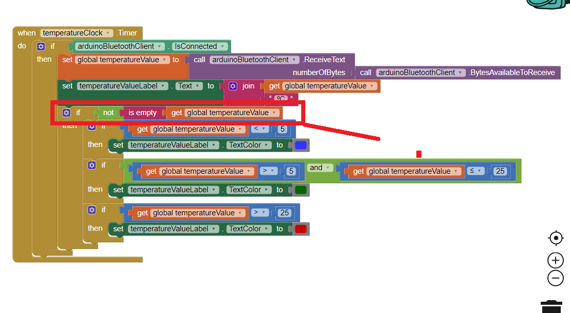
We can solve this by adding an additional if statement that before running the comparison blocks, checks whether the temperatureValue variable was already initialized. We can do that by using the “is empty block” as shown below.

I’ve created new .aia and .apk files with that fix.
I’ll fix those issues on the eBook as well as taking into account your suggestions in the next eBook update.
Let me know if this fixes your issue.
Regards,
Sara
Hi Sara,
thanks for your efforts, however the modification you offered only serves as a temporary solution not a permanent one.
Specifically running Project_5_Temperature_Readings from your smart phone, can only run for only a few minutes, and then invariably will crash, displaying messages such as the following:” Bad arguments to <
The Operation < can not accept the arguments:,[2.50 22.50],[5]” .this message was displayed while the Arduino project_5_Temperature_Readings was running normally as could be seen by the debugger in the Serial Monitor, spitting out temperature values: 22.50, 22.50. And the Bluetooth device was also operating normally, as could be seen by the non-blinking LED. It is interesting to notice that the MIT inventor project_5_Temperature_Readings, somehow incorporated two successive temperature readings 22.50, and 22.50 (the first one of which was truncated down to 2.50) into a single reading therefore crashing the program.
the next reading incorporates three values as a single measurement: “Bad arguments to >
The operation > cannot accept the arguments:, [23.00 22.50 23.00],[5]”. Again both Arduino and Bluetooth devices were functioning normally.
In the third example we have “Bad arguments to <
The operation <cannot accept the arguments:, [-127.00-127.00],[5]
I was able to resolve this last error as not due to the MIT project but rather being a problem of the sensor being operating in the parasite mode. First by reviewing the Dallas library I found out in the DallasTemperature.h file the define statement DEVICE DISCONNECTED -127.
However because this error was not consistent(only popping up once a while, made me look for something in the hardware and Arduino side rather than the MIT inventor side
by running simple.ino (Files->examples->DallasTemperature->simple) I run this sketch which is virtually identical to project_5_Temperature_readings, only better because it runs the debugger:
……………………..
// Check if reading was successful
if(tempC != DEVICE_DISCONNECTED_C)
{
Serial.print("Temperature for the device 1 (index 0) is: ");
Serial.println(tempC);
}
else
{
Serial.println("Error: Could not read temperature data");
in other words the statement :if(tempC != DEVICE_DISCONNECTED_C) was not true meaning the device was DISCONNECTED.
But why? the sensor was less than a year old and had only been used a couple of time, I checked all the wiring and seemed OK.
I run another sketch and the sketch was able to identify that the device with index 0 was connected and it also gave me its address. By reading the specs for the DS18B20, I found out that ” In parasite mode, when the DS 18B20 is performing temperature conversions, or copying data from the scratchpad memory to EEPROM , the operating current can be as high as 1.5 mA.
This current can cause an unacceptable voltage drop across the 1-Wire pullup resistor, and is more current that can be supplied by Cpp(the parasite capacitor within the DS18B20). Maxim recommends the use of a MOSFET transistor to pull t the bus directly to the rail. First of all in the the project_5_Temprerature_Readings no MOSFET is using only the 4.7 K pullup connected to the DQ pin, which I think is an omission particularly since many a times especially if you draw power from a USB hub, ( as I do) there can be frequent changes in power demand as you might have increased power surges even due to unidentified sources (hackers). So instead of grounding the VDD pin I connected it to the Arduino 5V power pin.. ” The advantage of this method , is that the MOSFET pullup is not required, and the 1-Wire bus is free to carry other traffic during the temperature conversion time.
Since I implemented this change, I have never seen this error of -127 displayed again
but the other problems still remain. Having said that I have to admit that my knowledge of MIT inventor programming on a scale 0-100 is probably 5. The reason for that being that I just started a couple of weeks ago, and (here expressing my personal bias), I think there is an excessive amount of work in order to perform a simple task such as turning an LED ON/OFF or reading a sensor. Its like trying to crack a nut open using a 5 ton steam hammer. And this in lieu of the fact that most of the heavy lifting has been done by the libraries of OneWire and DallasTemperature. I frankly do not think you should use more than three four blocks as usually can be done with node-RED.
Cheers
George
…………………………………………
whenever I was getting this message on the smart phone was also getting the message:
“Error: Could not read temperature data” on the Serial monitor.
Hi George.
I don’t know why that happens in MIT App Inventor (aggregate 2 successive readings) – I’ll try to find a solution for that problem and then, I’ll share with you my results.
When you get -127 with the DS18B20, it means the sensor was not able to get temperature readings. It may happen whether the sensor is new or not.
To prevent crashing the app when you get -127, you can, as you referred add an if statement in your Arduino code. Also, putting the sensor in normal mode instead of parasite mode can be a better idea.
I’ll take another look at this project and see if I can find a solution. I’ll try to remove the if statements that add colors to the temperature and see if the problem remains…
Did you have problems with any other projects?
Regards,
Sara
Thanks for your efforts Sara,
What I would like to add though is the fact ALARM conditions are provided by the sensor itself so one does not have to generate those conditions in the MIT Inventor app. Specifically the 16 bit digitally stored temperature in the scratch pad memory is compared with user defined UPPER and LOWER ALARM LIMITS STORED in two 8-bit registers also in the scratch pad memory(EEPROM), Here is a program which is based on Arduino’s example sketches (Simple.ino, and ALARM.ino) modified and stripped down:
#include <OneWire.h>
#include <DallasTemperature.h>
// Data wire is plugged into port 2 on the Arduino
#define ONE_WIRE_BUS 2
// Setup a oneWire instance to communicate with any OneWire devices (not just Maxim/Dallas temperature ICs)
OneWire oneWire(ONE_WIRE_BUS);
// Pass our oneWire reference to Dallas Temperature.
DallasTemperature sensors(&oneWire);
// arrays to hold device addresses
DeviceAddress Thermometer;
void setup(void)
{
// start serial port
Serial.begin(9600);
Serial.println(“Dallas Temperature IC Control Library Demo”);
// Start up the library
sensors.begin();
// locate devices on the bus
Serial.print(“Found “);
Serial.print(sensors.getDeviceCount(), DEC);
Serial.println(” devices.”);
// search for devices on the bus and assign based on an index.
if (!sensors.getAddress(Thermometer, 0)) Serial.println(“Unable to find address for Device 0”);
// show the addresses we found on the bus
Serial.print(“Device 0 Address: “);
printAddress(Thermometer);
Serial.println();
Serial.print(“Device 0 Alarms: “);
printAlarms(Thermometer);
Serial.println();
Serial.println(“Setting alarm temps…”);
// alarm when temp is higher than 30C
sensors.setHighAlarmTemp(Thermometer, 30);
// alarm when temp is lower than -10C
sensors.setLowAlarmTemp(Thermometer, -10);
Serial.print(“New Device 0 Alarms: “);
printAlarms(Thermometer);
Serial.println();
}
// function to print a device address
void printAddress(DeviceAddress deviceAddress)
{
for (uint8_t i = 0; i < 8; i++)
{
if (deviceAddress[i] < 16) Serial.print(“0”);
Serial.print(deviceAddress[i], HEX);
}
}
// function to print the temperature for a device
void printTemperature(DeviceAddress deviceAddress)
{
float tempC = sensors.getTempC(deviceAddress);
Serial.print(“Temp C: “);
Serial.print(tempC);
Serial.print(” Temp F: “);
Serial.print(DallasTemperature::toFahrenheit(tempC));
}
void printAlarms(uint8_t deviceAddress[])
{
char temp;
temp = sensors.getHighAlarmTemp(deviceAddress);
Serial.print(“High Alarm: “);
Serial.print(temp, DEC);
Serial.print(“C/”);
Serial.print(DallasTemperature::toFahrenheit(temp));
Serial.print(“F | Low Alarm: “);
temp = sensors.getLowAlarmTemp(deviceAddress);
Serial.print(temp, DEC);
Serial.print(“C/”);
Serial.print(DallasTemperature::toFahrenheit(temp));
Serial.print(“F”);
}
// main function to print information about a device
void printData(DeviceAddress deviceAddress)
{
Serial.print(“Device Address: “);
printAddress(deviceAddress);
Serial.print(” “);
printTemperature(deviceAddress);
Serial.println();
}
void checkAlarm(DeviceAddress deviceAddress)
{
if (sensors.hasAlarm(deviceAddress))
{
Serial.print(“ALARM: “);
printData(deviceAddress);
}
}
void loop(void)
{
// call sensors.requestTemperatures() to issue a global temperature
// request to all devices on the bus
Serial.print(“Requesting temperatures…”);
sensors.requestTemperatures();
Serial.println(“DONE”);
float tempC = sensors.getTempCByIndex(0);
if(tempC != DEVICE_DISCONNECTED_C)
{
Serial.print(“Temperature for the device 1 (index 0) is: “);
//printf(“%02d”,tempC);
//sprintf(sz, “degrees Centigrade = %f”,tempC);
//Serial.println(sz);
Serial.println(tempC);
}
else
{
Serial.println(“Error: Could not read temperature data”);
}
// Method 1:
// check each address individually for an alarm condition
// checkAlarm(Thermometer);
// Alternate method:
// Search the bus and iterate through addresses of devices with alarms
// space for the alarm device’s address
DeviceAddress alarmAddr;
//Serial.println(“Searching for alarms…”);
// resetAlarmSearch() must be called before calling alarmSearch()
sensors.resetAlarmSearch();
// alarmSearch() returns 0 when there are no devices with alarms
while (sensors.alarmSearch(alarmAddr))
{
Serial.print(“ALARM: “);
printData(alarmAddr);
}
}
An here is a typical output on the Serial Monitor:
Dallas Temperature IC Control Library Demo
Found 1 devices.
Device 0 Address: 280700071C9601DB
Device 0 Alarms: High Alarm: 30C/86.00F | Low Alarm: -10C/14.00F
Setting alarm temps…
New Device 0 Alarms: High Alarm: 30C/86.00F | Low Alarm: -10C/14.00F
Requesting temperatures…DONE
Temperature for the device 1 (index 0) is: 29.50
Requesting temperatures…DONE
Temperature for the device 1 (index 0) is: 29.50
Requesting temperatures…DONE
Temperature for the device 1 (index 0) is: 30.00
ALARM: Device Address: 280700071C9601DB Temp C: 30.00 Temp F: 86.00
Requesting temperatures…DONE
Temperature for the device 1 (index 0) is: 30.00
ALARM: Device Address: 280700071C9601DB Temp C: 30.00 Temp F: 86.00
Requesting temperatures…DONE
……………………
So in the 2nd line the program correctly identifies there was only one sensor, then in the third line it gives the ID of the device with zero index, in the next line it prints out the user stored values for high and Low Alarms in degrees Celcius( the degrees F are calculated using a table stored in the scratch pad), etc
after requesting a temperature reading, we get a printout of it and this continues till we get an ALARM condition when it is equal or higher to 30 degrees Celsius. this will continue as long the condition exists. when the temperature falls below 30 degrees the flag is reset to zero. Similarly when the temperature falls below -10 degrees the LOW ALARM is triggered and persists as long as the temperature is lower than -10 degrees
interfacing with MIT inventor requires that all string statements be commented out otherwise the project will crash.
cheers
Hi George.
You can set alarms with the DS18B20. But the aim of the project was to keep the Arduino code simple, so we just used a simple code to request the temperature and sent it via Bluetooth.
You can send the alarm flags to MIT App Inventor to set the colors. However, you would still need to add some if statements to check the flag value and set the colors accordingly.
I’ve tested what I’ve said previously: deleted the if statements to set the colors and just show temperature in black color.

The app worked well and didn’t crash. But sometimes, if your smartphone goes in sleep mode, when you open the app again, it will have some aggregate readings. These disappear after 1 or 2 seconds.
Regards,
Sara
Ok Sara,
I had already done this. in fact I do that with every MIT inventor project , before the project is completed just to check how it is evolving, or if I do not have all the tools for the project, like the project which required a smart phone with an accelerometer, I did not have the accelerometer, so i just skipped that part and compiled the program, and it worked just fine without it.
But here are the issues that I had with this project which I have solved. first the change of the colors of the temperature readings is not a realistic one. a more appropriate scenario would be a Red LED turned ON at HIGH ALARM, and a blue one at LOW ALARM.
The second issue I had with this project was the fact that the default 12 bit resolution of the DS18B20, is overrun when the OneWire library is called in and is set to 9 bits resolution. the problem with having a 9 bit resolution means you can resolve temperature in degrees Celsius at best down to 0.5 C.
your project displays temperature readings to the second decimal point which is bogus. for example a temperature that should have been displayed as 23.5 C, is displayed as 23.50 C. and we know the second decimal is not significant therefore worthless. But the worse par of the 9 bit resolution, is the fact it is very noisy.
For example a temperature displayed as 23.50, is displayed as 23.00, or 24.00 the next couple of seconds, which really annoying and unreliable. Well I fixed this problem by restoring the sensor’s default resolution of 12 bits capable of a resolution of 0.0624 C, using this : sensors.setResolution(deviceAddress, 12);
This and the fact I made some other adjustments as you will see in my program made the temperature readings extraordinarily stable and accurate. The other part has to do with the way the temperature is acquired by the sensor. At 9 bits resolution the maximum conversion time is 93.75 ms. At 10 bits 187.5 ms, at 11 bits 375 ms, and at 12 bits 750 ms. At 12 bits resolution if you have several sensors attached to the same wire it becomes a significant delay, the way you can deal with this is, you can use async reading so you do not have to wait for the conversion process to complete. you are taking your readings, and read them later: sensors.setWaitForConversion(false);//async conversion.
By setting the function argument to false, you essentially tell the sensor, do not wait for the completion of the conversion, when you issue : sensors.requestTemperatures();
then you set the flag true: sensors.setWaitForConversion(true); if you bracket these statements between a start = millis(); and a stop = millis(); and you subtract the two: stop-start you get the elapsed milliseconds.
this is called a non-blocking async event.before and after. If you do not incorporate the sensors.setWaitForConversion(false); and sensors.setWaitForConversion(true); its called blocking before and after.
the final step towards improving the whole thing was I replaced using : (sensors.getTempCByIndex(0));
with float tempC = sensors.getTempC(deviceAddress);. this is because (sensors.getTempCByIndex(0)); is very slow due to the fact is designed to go after each sensor in the wire.
here is an Arduino sketch:
/*
* Rui Santos
* Complete Project Details http://randomnerdtutorials.com
*/
#include <OneWire.h>
#include <DallasTemperature.h>
// Data wire is connected to the Arduino digital pin 2
#define ONE_WIRE_BUS 2
// Setup a oneWire instance to communicate with any OneWire devices
OneWire oneWire(ONE_WIRE_BUS);
unsigned long start = millis();
unsigned long stop = millis();
// Pass our oneWire reference to Dallas Temperature sensor
DallasTemperature sensors(&oneWire);
DallasTemperature Thermometer;
void setup() {
// Start up the library
sensors.begin();
sensors.setResolution(deviceAddress, 12);
// initialize serial communication at 9600 bits per second:

Serial.begin(9600);
}
void loop() {

delay(2000);
// Call sensors.requestTemperatures() to issue a global temperature and Requests to all devices on the bus
start = millis();
sensors.setWaitForConversion(false);
sensors.requestTemperatures();
sensors.setWaitForConversion(true);
stop = millis();
//Serial.println(stop-start);
//-----------------------------------
/* start = millis();

sensors.requestTemperatures();

// stop = millis();
// Serial.println(stop-start);
//---------------------------------- */
// Celsius temperature

float tempC = sensors.getTempC(deviceAddress);

//Serial.println(tempC);
// Serial.println("\n");
// Check if reading was successful
if(tempC != DEVICE_DISCONNECTED_C)
{
// Serial.print("Temperature for the device 1 (index 0) is: ");
Serial.println(tempC);
Serial.println("\n");
}
else
{
Serial.println("Error: Could not read temperature data");
}
}
cheers
Hi George.
You’re right. Using our default code, the resolution is not the best (0.5ºC) as you’ve said with 9-bit resolution. And yes, the second decimal point is not significant.
Thank you so much for sharing your code. You’ve made a good usage of the functions provided by the DallasTemperature library. Now you can get readings with better resolution.
Are the readings more stable? Or do you still notice some inexplicable ups and downs?
Regards,
Sara
Hi Sara, thanks,
No I have not made any more measurements, because I have moved on to other projects. However I am pretty sure the readings are going to be very stable and very accurate. I might return back to address the DS18B20, because you use this detector in many of your projects. And although it is a pretty old detector, IMO is an outstanding piece of human ingenuity.
cheers