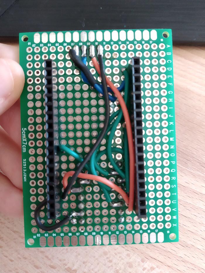
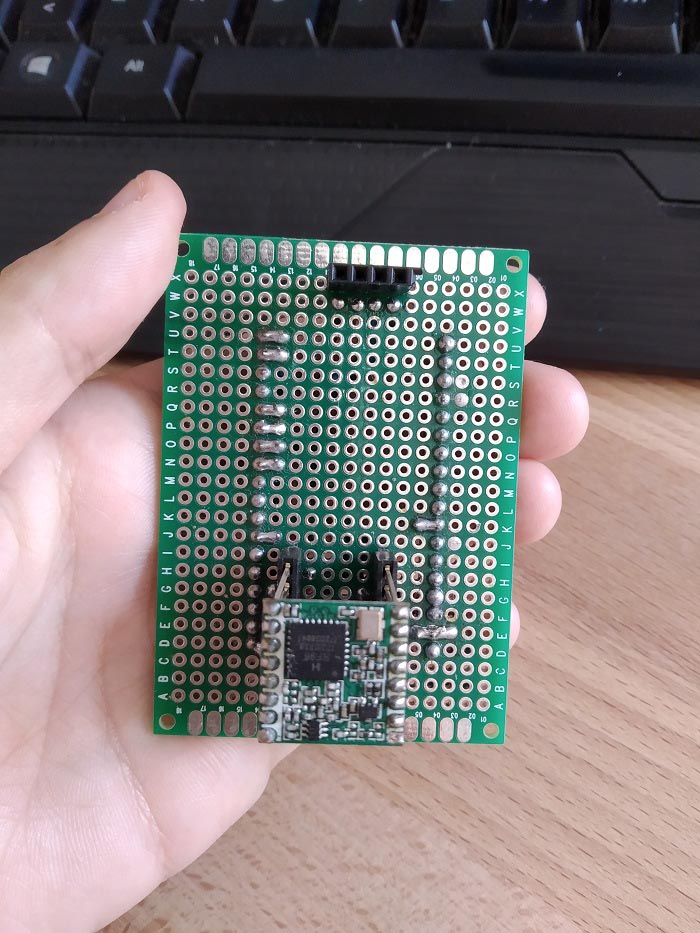
In esp32 Module 6, Unit 2 stripboards are introduced for connecting components. For some of us this is new, so just wondering if you could provide a little guidance with respect to the LoRa unit. I did some searching but it looks a bit complicated using cutting tools, etc. Not sure how to proceed.
Hi Jack.
We don’t have any tutorials about using stripboards.
But, it is not difficult at all.
Unlike a breadboard, none of the holes of a stripboard are connected.
You just need to place your components on the stripboard. It can be anywhere in the stripboard. However, depending on the circuit, it may be more practical to have the components in a certain layout.
Then, solder the components to the stripboard.
Finally, you need to cut some wires and solder together the pins that should be connected.
For example, in case of that specific project, you need to cut a wire that goes from the RST pin of the LoRa module to the ESP32 GPIO 14.
Because we don’t want to solder the ESP32 permanently (because we may want to use it for another project, it is more practical to upload code, and we may damage the ESP32 while soldering), we solder header pins (like these: https://makeradvisor.com/tools/female-pin-header-socket/) and then we connect the ESP32 to those header pins.
For you to have a better idea, here’s some photos of the stripboard of that project.


I hope this helps.
Regards,
Sara
Thanks Sara. That makes it much more clear and practicable. I was confused by some presentations on YouTube that suggest the holes are connected by copper strips and breakpoints need to be created with cutting tools.
For future reference, where a more permanent configuration is placed in the field, such as outdoor weather or soil stations, I would assume soldering directly to the board might be more reliable? Perhaps even using conformal coatings? I see in Project 4 (esp32) it still shows using breadboards, but I would think moisture or/and insects could compromise the unit, although I suppose the IP65/IP67 rated enclosures would prevent that.
Hi Jack.
Those stripboards are probably different than the ones we use.
Soldering a permanent circuit is more “reliable” because the jumper wires sometimes are loose and disconnect.
If you are talking about soldering the ESP32 directly without using the header pins, it doesn’t make much difference in my opinion. When you connect the ESP32 to the header pins, they are very tight.
If you don’t use the header pins, you need to be careful when soldering to prevent damaging the ESP32.
The enclosure we use protects the circuit well, even in a breadboard. But, for a final solution, I think it maybe better to use a more permanent circuit, if you have the means for that. Otherwise, the breadboard may work just fine as well.
Regards,
Sara
In the picture above, what is the method used to create the solder bridges?
https://drive.google.com/open?id=1C6-LwWGFO_Wq-MYONq2fOawhw2GOYHoh
I am finding it very difficult, and often create shorts to neighboring bridges, or they melt away and I have to start over. Very frustrating. There must be a trick you use?
Hi Jack.
There isn’t any trick.
Using a good soldering iron and good solder makes it easy.
I just put a lot of solder between the pins I want to connect. When you have a “bridge”, remove the soldering iron before moving the solid solder away – it helps keeping the bridge in place while it doesn’t get “solid”.
Regards,
Sara